ER (Entity Relationship Model) in DBMS
What is the ER (Entity Relationship) Model?
The Entity Relationship (ER) model is one of the graphical models that are used to depict concepts of a database. Data flow diagram, DFD for short, was initially created in 1976 by Peter Chen, for use in illustrating the relationships between elements of a database. ER model is a set of symbols and diagrams that facilitate the modeling of entities and the relationship between them and the attributes of entities.
Key Components of the ER Model
The ER model consists of three primary components: This framework is composed of three classes namely: entity, attributes, and relation.
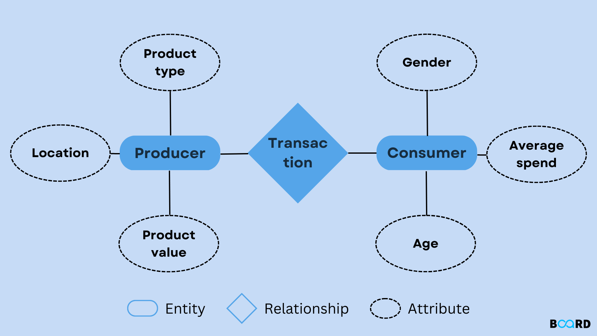
1. Entities: An entity is therefore any item, idea, or occurrence that the database has information about. In a given ER diagram, entities stand as rectangular shapes. They can either be an actual item like ‘Employee’ or ‘Product’ or can be ideas or concepts like ‘Course’ or ‘Department’ & etc. Every element has a special number, called the primary key, to differentiate one occurrence of the entity from another.
2. Attributes: Specific to the BOM model, attributes are the qualities or features intrinsic to the related entity. For instance, an “Employee” entity may have attributes such as Name, Employee ID, and salary. In the ER model, the attribute is depicted as an oval shape and is joined to its corresponding entity by a line. Attributes can be classified into several types:
- Simple attributes: Cannot be subdivided any further (For instance, Name).
- Composite attributes: It can be further partitioned into other attributes (for instance, Full Address is viper into Street Attribute, City Attribute, and Zip Attribute).
- Derived attributes: In this case, depends on the nature and relationship between two attributes; where an attribute can be derived from another attribute.
- Multi-valued attributes: Multidimensional attributes such as Phone numbers.
3. Relationships: They are defined as any type of communication or connection between two or more formally integrated units. In an ER diagram, binary relationships are illustrated by a diamond. For example, the “Employee” entity can be connected to a “Department” entity meaning an employee serves in a specific department. Relationships can be classified as:
- One-to-one (1:1): A one-to-one relationship is whereby one particular entity is linked with one particular of another entity.
- One-to-many (1:M): One member of an entity is linked to many members of another type of entity.
- Many-to-many (M: N): One form of one entity relates to another form of another entity.
Types of ER Models
Subsequently, several extensions of the original ER model have been proposed for different forms of databases and requirements. These variations are:
1. Enhanced ER Model (EER): The EER (Enhanced ER) model is an extended version of the basic ER model; the new features it includes are:
- Generalization and Specialization: Kinds of connections that form the hierarchy between superclasses and sub-classes. For example, a Vehicle refers to a pattern and the concrete implementations can include a Car and a Truck.
- Aggregation: The possibility of using a relationship set as the entity at a higher level.
- Inheritance: Subentities are those entities that include attributes and relationships of higher entities.
2. Relational Model: Though is not an ER model, the relational model is actually employed together with ER diagrams in actual physical modeling of databases. It represents data in tables or relations and uses keys to define relationships between the tables.
ER Diagram
ER diagram stands for Entity Relationship diagram where you represent Entity Relationship Model. It reflects entities, their characteristics, and interactions between them. An ideal ER diagram can be used as a guide to creating a database and would guarantee an account of all elements in the database and the relationship between them. Here’s a basic example of an ER diagram:
- Entities: Employee, Department
- Attributes: Workers (ID, Name, Post), Divisions (Dept_ID, Description).
- Relationship: Works_in (Not a one-to-one relationship between Employee and Department)
An ER diagram would depict an ‘Employee’ rectangle, a ‘Department’ rectangle, and a diamond shape within it dealing with ‘Works_in’. These attributes would be placed in ovals that are adjacent to the entities in which will be contained.
Steps to Create an Entity Relationship Diagram
Creating an Entity Relationship diagram involves several steps:
- Identify the Entities: First, we need to define the principal objects of your system. These could be tangible items, ideas, or phenomena that are essential for the design of the database in analysis.
- Determine the Attributes of Each Entity: After identifying entities, that define them by their attributes. It involves choosing which attributes are needed for each of the entities and how they are connected.
- Establish Relationships Between Entities: Identify the relationship between entities. For instance, if we already have two basic entities such as “Employee” and “Department,” you might require a segmented relationship, for instance, “Works_in,” to demonstrate that employees are in departments.
- Define Cardinality: Cardinality defines how many occurrences of one entity can be associated with another entity. The four common cardinalities are one-to-one, one-to-many, many-to-one, and many-to-many.
- Draw the ER Diagram: Entities should be depicted with rectangles, attributes with ovals, and finally relationships with diamonds. Join these components with straight like a straight line. Last but not least, identify the cardinality for every relation of interest.
Benefits of Using an ER Model
- Clear Database Design: The ER model lends part of acknowledgment in giving a simple picture of how the database looks like and hence can be easier in making communication about the structure.
- Helps in Data Organization: Used together with other approaches, it aids in sorting out information and data in a certain format that makes it easier to manage the information as well as find what is required.
- Ensures Consistency: The relationships and rules prescribed in the ER diagram help to maintain, and check, data consistency and integrity as they stipulate the working of data elements.
- Facilitates Database Normalization: As a basis for database normalization and for the elimination of redundancy in data storage, the ER model returns entities and relationships in areas as a strong groundwork.
- Improves Data Integrity: Because relationships, constraints, and key attributes are clearly specified in the ER model, high levels of data integrity and accuracy are injected into the database.
Challenges and Limitations of the ER Model
Before moving further let us discuss the challenges and limitations associated with the Entity-Relationship Model
- Complexity in Large Systems: Another disadvantage of using ER diagrams is that since big projects involve several related entities, the diagrams become complicated and complicated to organize.
- Lack of Support for Dynamic Data: Lack of Support for Dynamic Data: Like the relational model it needs to be enhanced to support temporal data or dynamic data attributes.
- Doesn’t Define Actual Database Schema: What the ER model does is provide a conceptual design of the database but does not specify how the real database is to be implemented let alone optimized.
- Difficulty Handling Many-to-Many Relationships: Oddly enough, the concept of many-to-many relationship is clearly defined in the ER model, yet representing many-to-many relationships in the diagrams and finally in the relational database can be problematic.
Mark Lesson Complete (ER (Entity Relationship Model) in DBMS)
Mark Complete
Bookmark